Next term at Rushey Mead Primary, we are trialing the Primary CAS Hub Micro Bit Project.
Aim of the project
The DfE has identified a number of ‘opportunity areas’ DfE announcement areas where there is an opportunity to create more computing support for teachers in deprived areas. This project aims to create a programme of support for primary schools in those areas (or in other areas that are classed as being deprived) focusing on a cross-curricular scheme of work which embeds the development of pupil’s computational thinking skills and which uses the micro bit with the aim of enhancing learning and motivation in KS2 pupils.
The project aims to enable a CAS Hub to provide the teachers in the project schools with the resources, skills and knowledge to confidently teach their pupils using the scheme of work and to provide ongoing support in terms of evaluating the effectiveness of the teaching and learning and to produce a case study that exemplifies the impact of project. Hubs that are able to find 2 or 3 schools that are in deprived areas and who are willing to get involved in running this project will be entitled to a free class set of micro bits, as will their project schools. These Micro Bits have been kindly sponsored by the Micro Bit
The resource pack on the CAS teacher resources site (free sign up required) includes a cross-curricular SOW based on the Ted Hughes Iron Man novel and involves the pupils building their own Iron Man model (D&T) and a micro bit controlled buggy (CS) and using their creation to retell an aspect of the Iron Man story (IT).
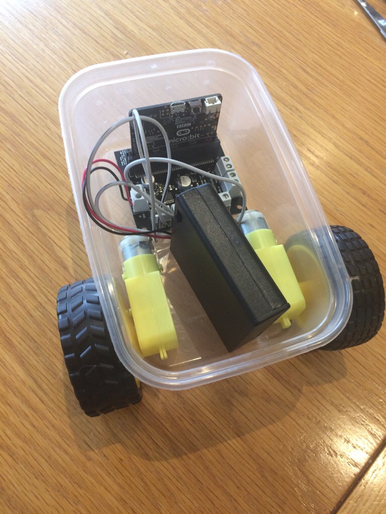
Building the buggy
Kitronik have very kindly got the project started by sending us enough kit to make 7 buggies and we will have microbits provided by the Microbit foundation. So it was my job in the holidays to check that this would actually work!
Building the buggy was straight forward, though I made a list of helpful tips to remind me of things I will need to sort when scaling this up at school with our children:
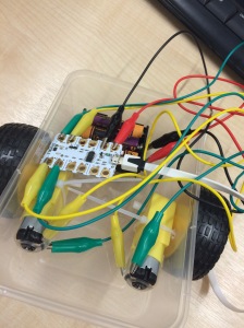
- We need a supply of wire to connect motors to motor board and a system to either pre-strip the wires for the children, or a handy teaching assistant dedicated to the job in class! Attaching the wires to the motors is fiddly and it may be easier to solder them on.
- When we punched holes in the lunch box, the instructions recommended using an electric drill, we thought a bradawl might work but it split the plastic, so resorted to hot wire instead. Again, this will need to be done ahead of time or supervised in the classroom.
- It took my husband quite a while to find an appropriate slot head screw driver with parallel sides and very narrow head (3 mm) that would fit the very small screws in the connectors that hold the wires from the motor and batter packs in place on the motor board. We will need a good supply of these in the classroom!
- Double-sided tape to stick the ball caster to the underside of the buggy worked really well.
- The lunch box itself needs to be big enough for the wheels to clear the rim of the box – ours *just* made it!
Coding the microbit
The next step was getting the motors working. With some help from the wonderful Lorraine Underwood who managed via twitter to point me in the right direction whilst marooned in her car with a sleeping toddler, I succeeded in getting both motors working so the buggy can move forward.
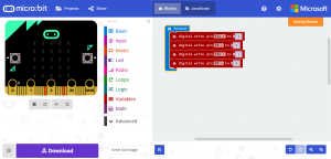
What had perplexed me initially was that the microbit looks to have 4 main pins (the large gold ‘holes’), however, there are in fact 16 pins that can be addressed and when the microbit is popped into the motor driver board it all looks a bit more complicated! Looking closely at the motor driver board, you can see that pins P12 and P8 control Motor 1 and P6 and P0 control Motor 2. I also needed to know the right block to use – under the ‘device’ or ‘pins’ blocks – ‘digital write (0,1)’.
Finally, on Lorraine’s recommendation (and to see if I could transfer what I’d learnt in one coding environment to another one), I wrote the code again in the JavaScript blocks PXT editor. My very simple code (shown right)
The next steps will be to make the buggy turn left or right and to add some degree of control over it, perhaps by using the buttons.

4 thoughts on “Micro:bit lunch box buggy”